Graphical Mapper and Scripting to Manage Data
Business Problem
When you want to integrate System A with System B, sometimes you need to manage the format of the data because they don’t have the same format. In ION we can achieve this goal with the use of Graphical Mapper and ION Scripting.
Requirements
- User Privileges to ION Desk
- Security roles: IONDeskAdmin
- Access to an Infor Cloudsuite
Tutorial
Difficulty: Medium
Estimated completion time: 45 Minutes
ION through the ION Connector is able to read and write data to different systems. These different systems can be databases, APIs, files, or queues, and each of these has a different format. You will see three different scenarios where using Graphical Mapper and ION Scripting you can manage the format of the data so that can be used by ION.
1. From JSON to BOD
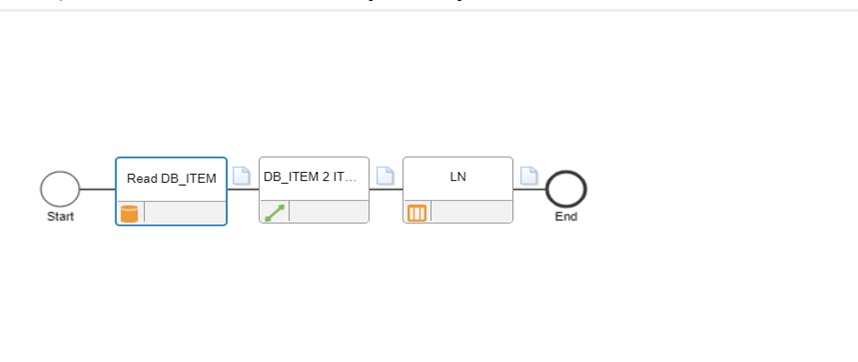
In the first scenario, you have a database that contains a table with records describing items you want to create in your ERP. Using the ION Connector of type database, you can read the records from the table in JSON format. to create the items in the ERP, the format of the data must be a BOD so you have to manage the format of the data. Below is the document flow and the description.
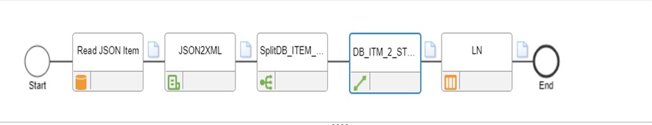
After reading the data in JSON format from the database you convert it into XML using the below ION Scripting
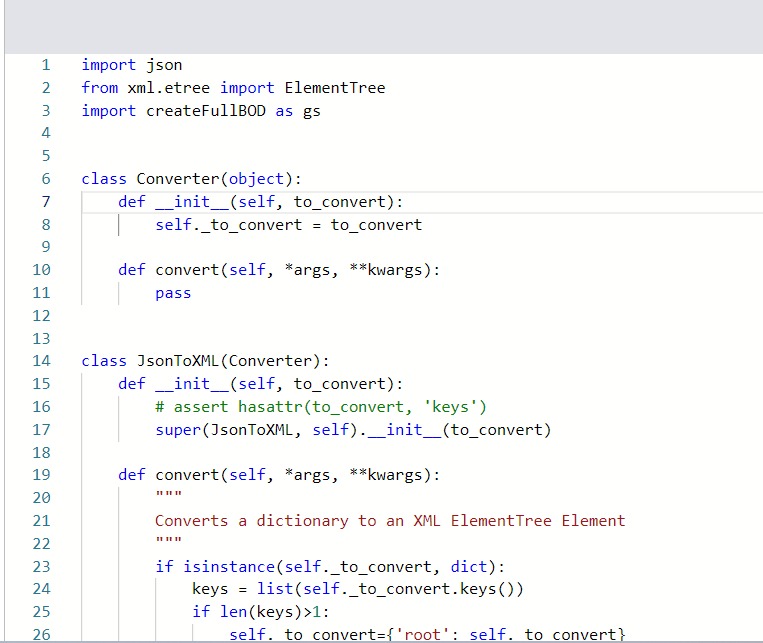
The script uses inheritance in the function definition to convert an incoming object to XML.
In the script, initially, a Converter class is defined which takes an object as a parameter.
The class in JsonToXML, which inherits from Converter class(parent/superclass).
The super method takes 2 arguments (JsonToXML, self) where JsonToXML is a subclass and self is an instance of the object to convert and is using a method “convert”).
The “convert” method is described below:
- If the input to the method is a “dictionary”, then all the keys of the dictionary are read in the form of a list.
- All the keys are read into a ‘root’ or main tag.
- Else, if the input to the method is a “list”, then all the elements are directly read into a ‘root’
- From the list, the first key is assigned as a “Root tag”.
- This “Root tag” is converted out as an XML “root” element of the tree which is the hierarchical data format for representing data.
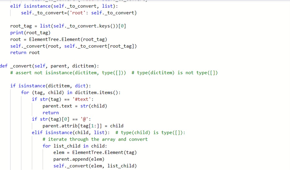
The next method (_convert) method is described below:
- If the object passed in is of a dictionary type, then loop through all the keys and child in it
- The text present in each tag is assigned to the parent tag
- Else if the top-most element does not contain text, then the key and child are attached as the element attributes.
- Else if the child element is of a type list, then iterate through all the elements in the list, and the tags are converted into element tree elements and then appended to the parent tag or main tag. Each element is converted in the same way.
- If all the above conditions turn false, then the value in the dictionary is assigned as text to the parent tag.
- This generates a “result” structure with all the root tags, children, and attributes.
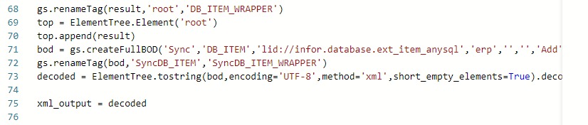
Finally, a full XML is generated with all the tags, child, and text elements. Further, the script uses a library called “Create FULL-BOD” to create the full structure of BOD dynamically.
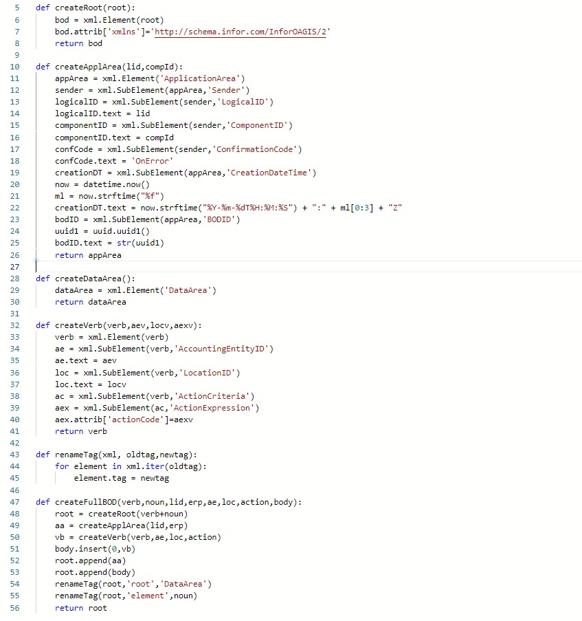
In the above script, the following functions are used to create a full BOD structure:
- “renameTag” is used to rename the XML generated above from ‘root’ to ‘DB_ITEM_WRAPPER’ which is the name of the custom Noun of the custom BOD.
- Then the ‘root’ element is converted as an XML tree element ‘top’ and the result is added to it.
- Then, the full structure of the XML is generated in the following way:
- by adding a root element with the proper namespace, Application area containing logical ID, component ID
- then, the verb, accounting entity, location ID, action criteria, and action expression are added as XML subelements.
- The bod is finally renamed from “SyncDB_ITEM” to “Sync_DB_ITEM_WRAPPER”
- Then, the final XML output is converted to a string using “toString” method with UTF-8 encoding to read any non-ASCII characters also and the final output is obtained as “xml_output
The Output from the ION Scripting component is in the form of Single-line XML.
Here, a splitter is used to split the single-line XML into a multi-line XML format.
Splitter formats each tag into a separate line to generate a multi-line XML.
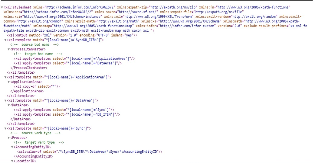
This multi-line XML is further converted into a standard BOD format by using the Mapper transformation (XSLT) as shown below
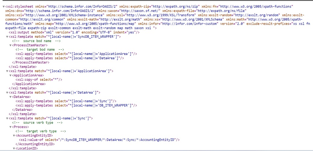
The XSLT converts the custom fields of the document into standard fields by using mapper transformations.
Here, a “Sync DB Item Wrapper” is converted to a “Process Item Master” following XSL Transformations.
Three main XSLT rules used in this transformation are:
- XSL template match: “XSL template match” contains rules to apply when a specific node is matched. The “match” attribute is used to associate a template with an XML element and add it to the output stream of transformation.
- XSL Value Of: “XSL Value Of” is used to extract the value of XML element and add it to the output stream of transformation.
- XSL- Copy Of: Creates a copy of the current node.
Steps:
- First, the source BOD name is identified and mapped to a target BOD name using template match()
- The “Application area” of the Target BOD is mapped as the same / copy as that of the Source BOD. Hence the fields, Logical ID, Component ID, Confirmation Code, Creation Data time and BODID values are copied from Source to Target BOD.
- In the “Data Area”, the verb “Sync” is converted to “Process” and the values of Accounting EntityID and Location ID elements within it are copied the same.
- The ActionCriteria tag with the actionCode is copied as it is.
- Then next noun “DB_ITEM_WRAPPER” is selected in the Source BOD and converted to “ITEM MASTER” in the Target BOD.
- The value of the ID inside the Item tag is converted into ItemID tag
- The value of the description is selected in the Description tag.
- The “Classification” tag is mapped for Groups and types of 2 elements inside the DB Item master tag and both the element types and groups are copied using a “value-of” rule.
- The “BaseUOMCode” tag is mapped for the UOMA Code of both items.
- The remaining items inside the Source BOD are mapped inside the “User Area” of the Target BOD.
- In the User Area, the “Item_EXT” tag is defined with the values of Colour, Height, Width, Depth, UOMB same as the SourceBOD values.
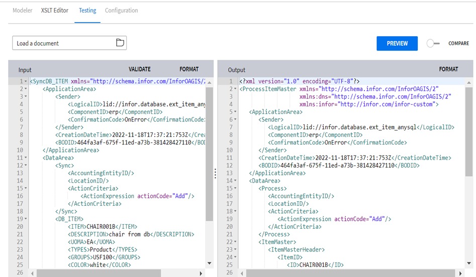
- This completes the XML BOD mapping from SourceBOD to a standard Infor OAGIS BOD using XSLT rules. The final output of XSLT is shown below.
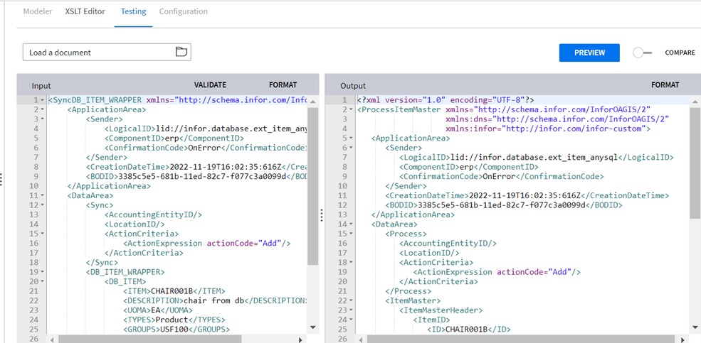
The final output as shown above is integrated into LN.
2. From custom BOD to standard BOD
The second scenario describes the sequence of steps to read an item table with a stored procedure to generate a custom BOD, then with a mapping to convert to Process.ItemMaster BOD and then send to LN for creating an item in LN.
The custom message is generated from the Database Connection point (through an Enterprise Connector) which was explained in part 1 of the tutorial (Customize Object Schema) using a Stored Procedure. The generated message is in XML format.
The XML is further converted into a standard Infor BOD format by using a Mapper transformation (XSLT) as shown below.
The XSLT converts the custom fields of the document into standard fields by using mapper transformations. Here, a “Sync DB Item” is converted to a “Process Item Master” following XSL Transformations.
Three main XSLT rules used in this transformation are:
- XSL template match: “XSL template match” contains rules to apply when a specific node is matched. The “match” attribute is used to associate a template with an XML element and add it to the output stream of transformation.
- XSL Value Of: “XSL Value Of” is used to extract the value of XML element and add it to the output stream of transformation.
- XSL Copy Of: Creates a copy of the current node.
Steps:
- First, the source BOD name is identified and mapped to a target BOD name using template match().
- All the “Sync” verbs are converted to “Process” verbs.
- The “Application area” of the Target BOD is mapped as the same / copy as that of the Source BOD Thus the fields, Logical ID, Component ID, Confirmation Code, Creation Data time, and BODID values are created as a copy from Source to Target BOD.
- In the “Data Area”, the verb “Sync” is converted to “Process” and the values of Accounting EntityID, Location ID, and Action Criteria elements within it are copied.
- The ActionCriteria tag with the actionCode is copied.
- Then next noun “DB_ITEM” is selected in the Source BOD and converted to “ITEM MASTER” in the Target BOD.
- The value of ITEM is copied as ITEM ID in the target BOD.
- The value of the Description is selected into the Description tag.
- The “Classification” tag is mapped for Item Groups and Item types of 2 elements inside the DB Item master tag and both the element types and groups are copied using a “value-of” rule.
- The “BaseUOMCode” tag is mapped for the UOMA Code of both items.
- The remaining items inside the Source BOD are mapped inside the “User Area” of the Target BOD.
- In the User Area, “Item_EXT” tag is defined with the values of Color, Height, Width, Depth, UOMB copied from SourceBOD values.
- This completes the XML BOD mapping from SourceBOD to a standard Infor OAGIS BOD using XSLT rules as shown below.
- The final output BOD is shown below.
In the final step, the above-generated Process.ItemMaster is sent to an application(LN) for creating an item in LN.
3. From CSV file to standard BOD
The third scenario describes the process to read a CSV file as an item from a 3rd party and convert the custom BOD to Process.ItemMaster and create an item in LN.
The CSV file is read from a Shared Folder which was explained in part 1 of the tutorial (Customize Object Schema) and generates a custom BOD. This BOD (Sync.External_Item) is converted to an Infor standard BOD (Process. ItemMaster) to create an item in LN.
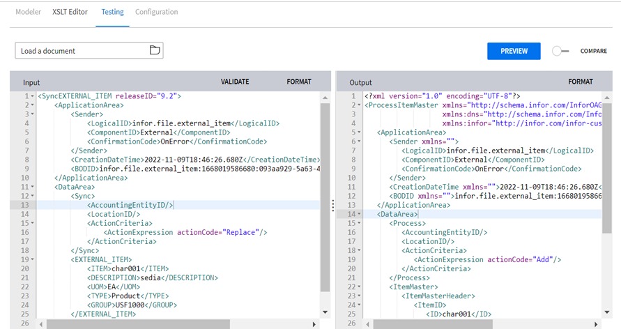
This custom BOD is further converted into a standard BOD format by using a Mapper transformation (XSLT) as shown below
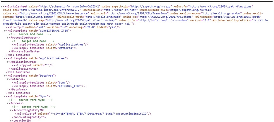
The XSLT converts the custom fields of the document into standard fields by using mapper transformations. Here, a “Sync External_Item” is converted to a “Process Item Master” following XSL Transformations.
Three main XSLT rules used in this transformation are:
- XSL template match: “XSL template match” contains rules to apply when a specific node is matched. The “match” attribute is used to associate a template with an XML element and add it to the output stream of transformation.
- XSL Value Of: “XSL Value Of” is used to extract the value of XML element and add it to the output stream of transformation.
- XSL- Copy Of: Creates a copy of the current node.
Steps:
- First, the source BOD name is identified and mapped to a target BOD name using template match().
- All the “Sync” verbs are converted to “Process” verbs.
- The “Application area” of the Target BOD is mapped as the same / copy as that of the Source BOD Thus the fields, Logical ID, Component ID, Confirmation Code, Creation Data time, and BODID values are created as a copy from Source to Target BOD.
- In the “Data Area”, the verb “Sync” is converted to “Process” and the values of Accounting EntityID, Location ID, and Action Criteria elements within it are copied.
- The ActionCriteria tag with the actionCode is copied.
- Then next noun “DB_ITEM” is selected in the Source BOD and converted to “ITEM MASTER” in the Target BOD.
- The value of ITEM is copied as ITEM ID in the target BOD.
- The value of the Description is selected in the Description tag.
- The “Classification” tag is mapped for Item Groups and Item types of 2 elements inside the DB Item master tag and both the element types and groups are copied using a “value-of” rule.
- The “BaseUOMCode” tag is mapped for the UOMA Code of both items.
- The remaining items inside the Source BOD are mapped inside the “User Area” of the Target BOD.
- In the User Area, the “Item_EXT” tag is defined with the values of Colour, Height, Width, Depth, UOMB same as the SourceBOD values.
- This completes the XML BOD mapping from SourceBOD to a standard Infor OAGIS BOD using XSLT rules as shown below.
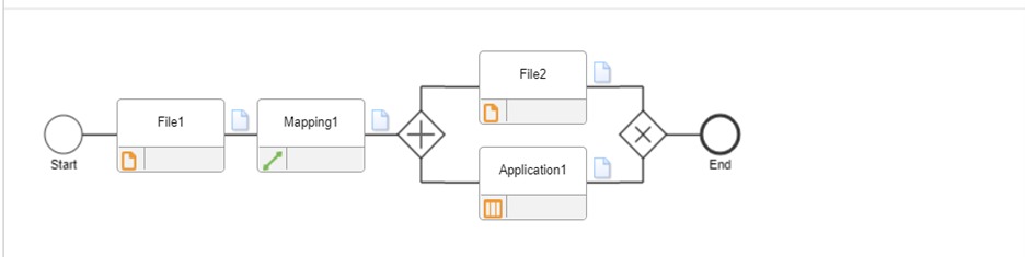
In this final step, the Process. ItemMaster generated in the previous step is further sent to a file and application using a Parallel flow.
Using a Shared Folder transfer protocol, the Process.Itemmaster is sent to a Target File(file2) for storage.
Further, the Process.ItemMaster is sent to an application (LN) to create an item in LN.
Downloads
Resources
Online help documentation: